
TECHNOLOGY INTROCUCTION
TECHNOLOGY
INTROCUCTION
Integrated Drive GXM Shifting Technology #2
S·R Shifting (Star Ratchet Shifting)
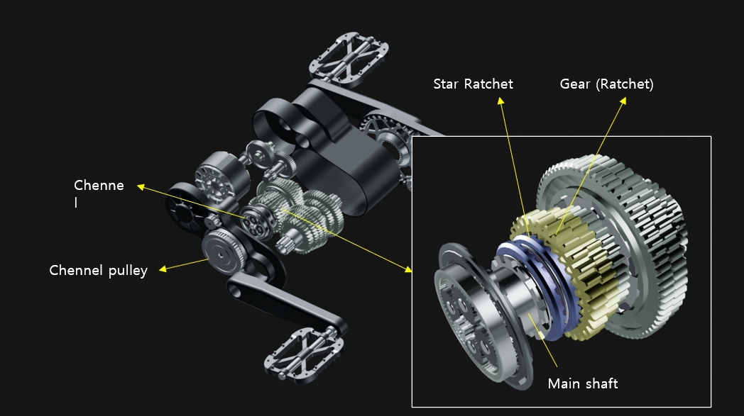
S·R Shifting refers to a mechanism that engages and disengages the main shaft and gears using a star ratchet.
Conceptually similar to an automotive dog clutch, this structure provides high durability under load.
In this system, gears remain free-spinning on the shaft, while the star ratchet is fixed to the main shaft and rotates with it, yet is able to slide axially.
The key function of this technology is the controlled selection and positioning of a specific star ratchet to engage or disengage the desired gear.
Integrated Drive GXM Shifting Technology #2
S·R Shifting (Star Ratchet Shifting)
S·R Shifting refers to a mechanism that engages and disengages the main shaft and gears using a star ratchet.
Conceptually similar to an automotive dog clutch, this structure provides high durability under load.
In this system, gears remain free-spinning on the shaft, while the star ratchet is fixed to the main shaft and rotates with it, yet is able to slide axially.
The key function of this technology is the controlled selection and positioning of a specific star ratchet to engage or disengage the desired gear.
Integrated Drive GXM Shifting Technology #2
S·R Shifting
(Star Ratchet Shifting)
S·R Shifting refers to a mechanism that engages and disengages the main shaft and gears using a star ratchet.
Conceptually similar to an automotive dog clutch, this structure provides high durability under load.
In this system, gears remain free-spinning on the shaft, while the star ratchet is fixed to the main shaft and rotates with it, yet is able to slide axially.
The key function of this technology is the controlled selection and positioning of a specific star ratchet to engage or disengage the desired gear.
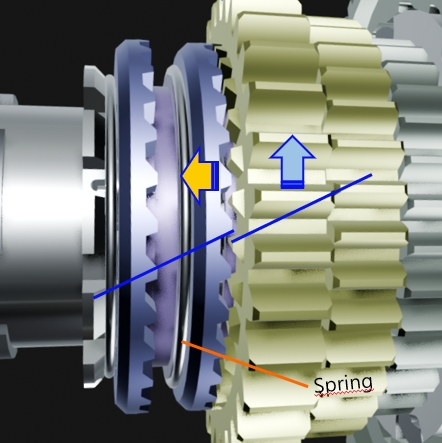
As illustrated in the left diagram, the diagonal blue lines indicate that rotational force from the gear can push the star ratchet toward the left during engagement.
To transmit torque, this axial movement must be restrained.
In this structure, a spring performs this retaining function, keeping the star ratchet engaged with the gear.
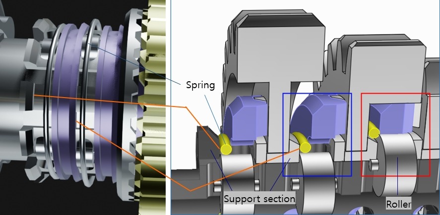
In the right diagram, the end of the orange line represents a structural stop.
When the star ratchet is pushed to this point, it disengages completely from the gear, allowing the gear to remain free-spinning.
When the spring is positioned between the support surface and the star ratchet, axial movement is restricted.
In this state, the ratchet and gear remain fully engaged and torque is transmitted.
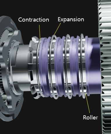
The diagrams below illustrate the compression and expansion behavior of the spring.
The spring is normally contracted, maintaining tension around the main shaft.
In this contracted position, it blocks star ratchet movement and maintains gear engagement.
The main shaft contains rollers that protrude outward in response to rotation of the internal camshaft.
When the rollers protrude, the spring expands and moves beyond the support boundary.
This creates clearance, allowing the star ratchet to slide and disengage.
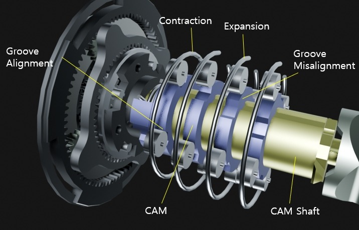
The internal view of the main shaft reveals CAM components fixed to the camshaft.
By actuating the channel, the camshaft and main shaft rotate in opposite directions at defined angular intervals.
Each CAM contains grooves at specific angular positions.
When a roller aligns with a groove, the spring contracts into the engagement position.
When the roller is misaligned with a groove, it is forced outward, expanding the spring and enabling disengagement.
The main shaft and camshaft rotate synchronously during normal operation, with relative angular changes occurring only when the channel is actuated.
This synchronized architecture maintains a stable shifting condition and prevents unintended gear transitions.